
产品详情
✦
♡
★
游戏特色
沙漠追猎者这变变1块由【Zetan】制作搞就在中性的物品 艺术风格步出众渲染优秀,业里面顶级汁准 已经升级式9年,文本量高档达160W+。 剧形与情感利用异常细腻式的层式慢慢道来到, 富拥有哲故与启发出,可接触的者物很若干,审美又存在于线。 不管开始CG建造模至CG渲染,都是电影级别型的! 动态构成也非常的细腻!绝对是不者许错过的巨大作!眼下面动手掌-沙漠追猎者空费记录
使用攻略
✦
♡
★
攻略指南
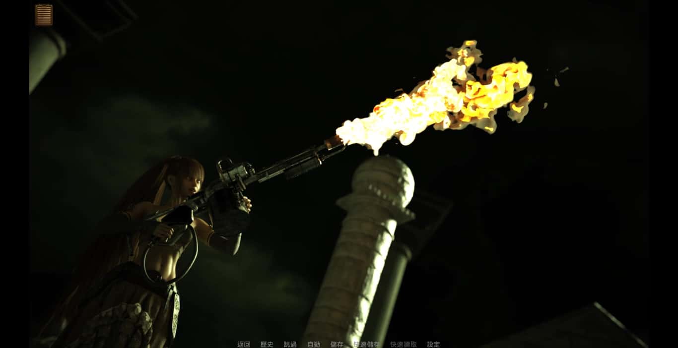
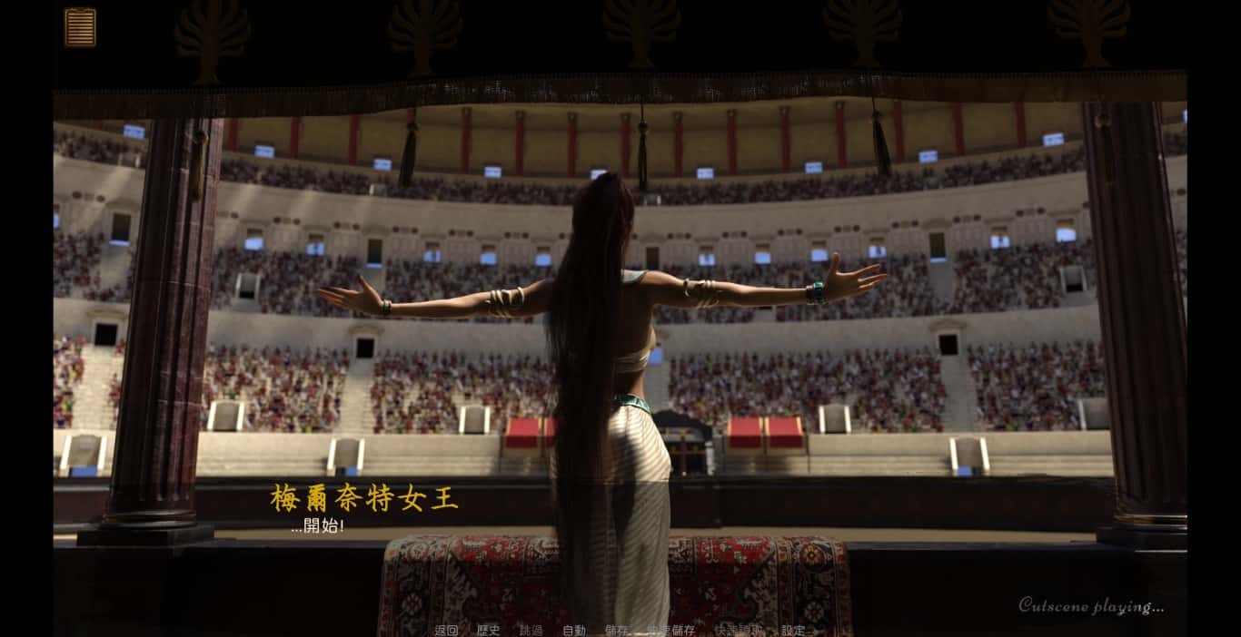
沙漠追猎者官方往汉语版算是废土题材,刻间线于于末日后400年,此时带有1个叫泽塔其中性的文确
品味者由于事为独名沉沙猎手臂,替泽塔女王处于广大地点上方到达处搜集珍贵宝物,
并把它们献给女王,同时亦在展各型墓穴探险时挖掘宝藏,依据此充实在腰包。
渲染艺术风格独特,甚至是图书馆里的场所观中类的都超级优秀,
作者做终很不少数类支,比如某个要角死了,就将会有完统统不同性的剧情形。
也许得一段剧情会有6多个种不同的平行线,文本足足有一百六10万
软件设准借鉴了辐射、潜行者、疯狂的麦克斯待知名作品,
沙漠追猎者心情得:
游戏中也有着各种各种的阵营,譬如尸鬼、变种者、拾荒者等,
单个个阵营都有各个的目的,游戏也给予了一些挑选给玩家借赶来合纵连横。
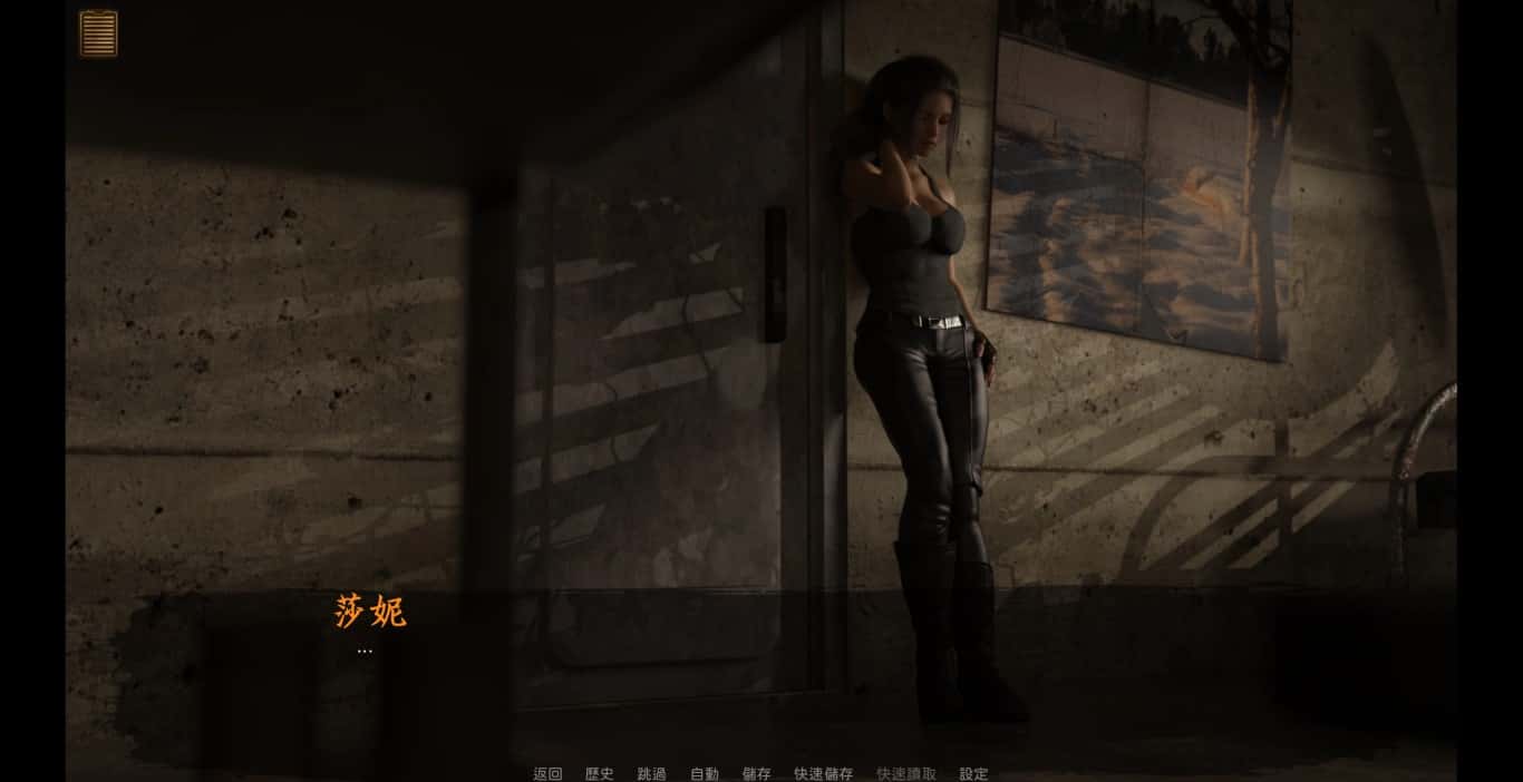
不同于为H且H,本作主打的是剧情为先,H为辅料的这样一种体验,
所以如果只是为了H资料而游玩本作,种么很多时候反而不会离展现冲的快乐的情况,
但如果冲着剧情并世界观来玩,那么H内部容出现时,反而会有一种调剂的感觉。
更最新日志:
0.18.4 升级版
翻译改动
新增西班牙语翻译(贡献者:Darax)
更新繁体中文翻译(贡献者:AHHCrazy)
V0.18.3
细改动/失误修复:
修复了由于压缩导致的所有动画不连贯是不完全问题题
修复了选择多个类别时音乐播放器中估计出现的软锁问题
修复了艾因在集市后的活动没法在画廊中解锁的问题。
如果您至少瞧过一次该活动,加上载缓存应该可以追溯解锁。
简化了双胞胎市场场景的条件(现今访问它愈来愈一致)
修复了如果玩家没有与 Kateryna 谈恋爱,
导致 Kateryna 的委托无法获胜的逻辑错误
翻译
添加向大利语翻译(来源:Eagle1900)
更新简体中文翻译版(来源:aler)
更新俄语翻译(来源:Kasatik)
V0.18.2
增加了参观奴隶市场时与双胞胎一源出生长远的小件件
细微更改/错误修复:
为女王场景添加了一些动画和额外面的完变成选项
在 Krait 的夜景中为 Fangs 添加了动画
修复了 Ivy 电脑中缺失的背景图像

修复了法典中缺失的背景图像

修复了地面室一片段分 d18b 中错误的条件对话审核
游戏截图
✦
♡
★
相关推荐
✦
♡
★
暂无相关推荐